


Planar Lipid Bilayer Electrophysiology
Electrophysiology is generally used to monitor the transport rates of ions across membranes through ion channels, where the rate of transport is measured as an ionic current [units of picoamps (pA)]. This phenomenon arises simply due to the fact that ions carry charges, and potentials, or voltages, [units of millivolts (mV)] can be applied across membanes. These potentials are called membrane potentials (Vm or Δψ), and they are either created electrically (e.g. by a battery with electrodes on either side of the membrane) or chemically by asymmetric solutions of ions (recalling the Nernst equation; see discussion below).
|
|
Planar lipid bilayer apparatus. Two compartments (cis & trans) are separated by a small hole, ~50 to 200 μm in diameter, wherein the membrane is formed. Each compartment contains a buffer with an electrolyte, typically 100 mM KCl. Electrodes are connected to each compartment (via salt bridges). The membrane potential is controlled (clamped) and the current is amplified using a voltage-clamp amplifier. A channel-forming preparation is added to the cis side, and channel formation is monitored by step-wise increases in the current due to the insertion of individual channels into the membrane. |
An interesting analogy can be drawn between biological ion channels and electronic circuits. Here the ion channel acts as a resistor (Rm) [units of Gigaohms (GΩ)], or in inverse terms, as a conductor (ρm = Rm-1) [units of picoseimens (pS)], and the phospholipid bilayer membrane acts as a capacitor. In simple bilayer electrophysiology setups, the membrane capacitance (Cm) is on the order of picofarads (pF). [See capacitance test.] As indicated above, the membrane potential is analogous to a battery in this model electronic circuit.
Planar lipid bilayers are used for functional studies of ion channel proteins using electrophysiological techniques. Two chambers (cis & trans) are separated by a thin, non-conducting partition within which a small hole is punched or drilled (Fig. 1). A lipid solution is then formed into a planar bilayer membrane in the hole. Ion channels can then be incorporated into the planar bilayer by directly applying the channel protein or fusing liposomes containing the channel of interest. A voltage-clamp amplifier (Fig. 2)—one that can deal with the large capacitances of these membranes—can then measure the ionic current through inserted channels.
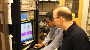 |
Single-channel planar bilayer setup. Axoclamp 200b voltage-clamp amplifer with a Digidata 1440A A/D acquisition setup. |
Single-channel recordings of ion channels have deepened our understanding of channel function, helping to elucidate mechanisms of membrane transport and cellular physiology. Patch clamping is a typical approach used to make single-channel recordings. For example, patch-clamped membranes allow for the study of the ion channel in its native surroundings. However, planar bilayer electrophysiology provides several distinct advantages, including control of the constituents on either side of the membrane, manipulation of lipid composition, and the ability to study rare or challenging channels inaccessible to patch-clamp methods. One major drawback is that planar lipid bilayers can have larger capacitances, because they have wider diameters than excised patches. These larger capacitances cause for a slow voltage response time due to the known resistor-capacitor- (RC-) filtering effect. All that said, each method offers complementary advantages and disadvantages for studying single ion channels.
Bilayer Rig
We have three Axon Axoclamp 200B voltage-clamp amplifiers (Fig. 2), which are now made by Molecular Devices. They interface with a custom bilayer perfusion cell (Fig. 3), which is based on the basic cell made by Warner Instruments.
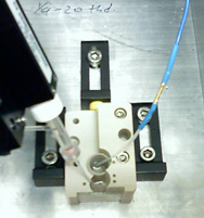 |
Bilayer cell. Top view of a bilayer cell, showing the cis and trans chambers, which are connected to the head stage by the Ag/AgCl electrodes. The bilayer cup in the rear has the small ~50- to 200-μm hole, wherein the lipid bilayer membrane is formed. |
Our bilayer cell is made out of PEEK, and the bilayer cup is made of white Delrin or polysulfone plastic. A Bilayer perfusion cell schematic is available. Schematics are also available so that the membrane can visualized via either a Polished polysulfone bilayer window or standard microscope slide with a Bilayer cell glass window support.
These instruments are capable of low noise recordings in single-channel mode as well as less sensitive multi-channel recordings. The sturdy metal Faraday cage (Fig. 4) blocks both sound vibrations and electrical noise (e.g., cell phones and AC power-line hum) from the experiment. Schematics for mounting the head stage and Schematics for the bilayer Faraday cage are available.
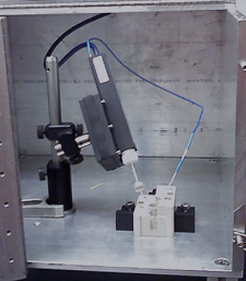 |
Amplifier head stage interfaced to a bilayer cell. Inside an aluminum Faraday cage is the bilayer cell connected to the voltage-clamp amplifer. The Faraday cage screens electromagnetic interference and sound vibrations from the sensitive head stage. |
Capacitance Test
The capacitance test is the practical means of determining the size and quality of an artificial bilayer membrane created during a typical planar lipid bilayer experiment.
Recall that a capacitor stores charges of opposite sign within conductive plates on either side of a dielectric medium (also known as an insulator). This situation is exactly represented by a phospholipid bilayer membrane (of low dielectric constant), whereupon two oppositely charged layers can build-up on either side. Thus a capacitor is analogous to a jar that can hold a set volume of water. [In fact, the first capacitor was a glass jar with metal plates on either side of the glass, and the first unit of capacitance was called a 'jar' (~ 1 nF).] As suggested in the above analogy, a pair of parallel disk conductors (of radius, r ) have a capacity that is directly proportional to the area of the disks and ε—the permittivity of the dielectric medium—and is inversely proportional to the thickness of the dielectric medium separating the disks, d: C = ε πr 2/d . This relationship is nice for bilayer membranes, which are formed in round holes, ranging in diameter from 50 to 200 μm. A useful number to consider is that phospholipid membrane has a capacitance per unit area of 1 μF/cm2. Thus, a 200 μm hole has a theoretical maxium of ~300 pF in capacitance! In reality, it is hard to achieve this ideal number (see below).
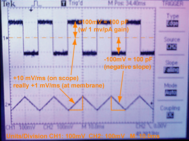 |
Practical details of the capacitance test. A photograph of the oscilloscope output during a capacitance test, using a model cell, which is not a membrane but rather an actual electronic circuit of a series capacitor (100 pF) and resistor. Model cells are often used to calibrate the voltage-clamp amplifier. Remember that the outputs are scaled in various ways. So, the applied triangle function appears to be ±10 mV/ms, but it is really ±1 mV/ms, as it is scaled 10× before being read by the oscilloscope. The current output square wave is ±100 pA, since the gain on the amplifier is 1 pA/mV. Recalling the capacitance is directly equal to the current when dV / dt is 1 V/s, the correct capacitance, 100 pF, is observed. We are using a Fluke 271 function generator [50% symmetric triangle wave, 50 Hz, 500 mV p-p (VhiZ)]. |
A convenient way to go about measuring membrane capacitance is to apply a symmetric triangle wave function as the membrane potential, where the rate of change in voltage is either ±1 V/s. Given the relationship between charge, q, in Coulombs (C) and voltage, V, for capacitance, C, is: C = q / V; you then can take the time-dependent derivative of this expression, i = dq /dt = dV/dt × C, where i is the instantaneous current [in units of Amps (C/s)]. Therefore, the current is directly equal to the capacitance (as dV/dt = ±1). Thus the current flows in either direction (depending on the sign of the voltage change with time) and appears in the oscilloscope as square-wave output. One-half of the peak-to-peak output is equal to the capacitance [of course after you include all the gain settings and output scaling factors in your particular setup (see Fig 5)].
Usually, the capacitance test is used to monitor membrane formation. Lipid solution is applied to the aperture with a paint brush or other means, and the initially observed capacitance is often lower than expected ideally. Bilayer then begins to spontaneously nucleate, and the capacitance gradually begins to climb. A 'good membrane' nearly approaches the limit expected above; e.g., a 200 μm hole yields ~200 pF in practice. A 'bad membrane' has a much lower than expected final capacitance. What is physically happening? When viewed optically, a thick torus of amorphous lipid surrounds the bilayer formed in the center. For a so-called 'good' membrane, this torus is much smaller than in a 'bad', poorly formed membrane.
Protocols
Salt Bridges — Using a microwave oven or hot water bath, melt a 2% agarose solution in 3 M KCl. The solution is kept liquid using a water bath maintained at ~95 °C. With a luer tubing adapter that connects a 10 cc syringe to ~1/16 in. tubing, connect a section that is ~60 cm-long to the luer adapter on the syringe and place the tubing under water in the hot water bath. Then very slowly draw the hot agar through the tubing to avoid air bubbles. After solidifying, cut the tubing into 10-cm-long bridges, placing them into ~25 ml of 3 M KCl in a sealed 50 ml conical tube. The agarose is the same type used in the DNA-separating gels common to molecular biology. Use 0.06 in. O.D. polyethylene (PE) tubing made by BD (Becton, Dickinson & Company). The BD Intramedic P/N is 427426, and it can be ordered from Fisher. (See current protocol on Google Docs.)
Lipid solution (DPhPC/decane) — Purchase ampules of DPhPC (1,2-diphytanoyl-sn-glycerol-3-phosphocholine) lipid from Avanti (P/N 850356C). The lipid comes dissolved in chloroform. Transfer the lipid solution to a clean capped test tube. Dry the lipid down under a dry nitrogen stream thoroughly at least 30 minutes after the last traces of solvent are visible. Then resuspend the dried lipid in n-decane to a final concentration of lipid of 30 mg/ml. Store at -20 ºC. N.B. the lipid may take several days to fully resuspend at -20 ºC to achieve its final consistency. (See current protocol on Google Docs.)
Folch solution — a solution containing chloroform and methanol in a 2:1 ratio. One of its uses is in separating polar from nonpolar compounds, for example separating nonpolar lipids from polar proteins and carbohydrates. We use Folch to clean our paint brushes and tubes that previously contained lipid solutions. Named after Jordi Folch-Pi (1911-1979), who is a famous lipid biochemist (See Jordi Folch Pi Biography.)

Jordi Folch-Pi — a neurochemist, who made contributions to lipid chemistry and biochemistry. |
Forming a membrane — Using a clean bilayer cup, paint the area around the hole on either side liberally with the lipid solution; let the cup dry thoroughly for 15 minutes; clean the paint brush in Folch several times; bathe either side of the hole completely in aqueous buffer; turn on the triangle-wave generator and observe the current as described in the capacitance test; re-dip the brush into lipid solution and gently wipe the bristles over the hole until a conductance-blocking seal is formed; observe the capacitance; and repeat the process of working the membrane either with a brush or air bubble until the desired capacitance is achieved. See P. Mueller, D. O. Rudin, H. T. Tien, W. C. Westcott, J. Phys. Chem. 67, 534 (1963) and Bilayer References.
Cleaning the bilayer cell & cup — Flush the bilayer cell with deionized water; soak the cell then in 0.05 M potassium phosphate, pH 12, using a swab to clean the lipid away from the hole; rinse thoroughly with water and then ethanol to aid in drying; and finally dry under a nitrogen stream. N.B. potassium phosphate is superior to NaOH as it is less harsh on the white Delrin cup and hole. (See Cleaning plastic bilayer cups.)
Single-channel protocols for anthrax toxin — Bilayer single-channel protocol.